C2 PROJECT
C2 Photo Album
album:June 2021
June 2021 working parties
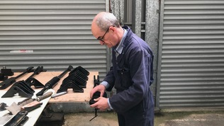
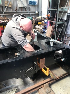
Chris trial-fits brake gear components after fettling those which did not quite fit previously.
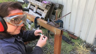
Helen checks the taper on a brake block retaining spike against a simple jig
Brake block retaining spikes in various stages of manufacture.
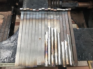
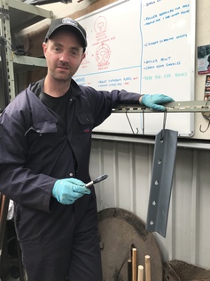
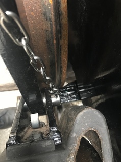
These long pins are used instead of split pins to retain the brake block carrier / hanger pins. Having formed the flattened spade ends this time, next working party we will drill holes in the spade ends and attach them to lengths of fine chain.
Slightly deepening the milled slot in one of the brake block carriers, to make it a better fit to the blocks.
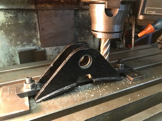
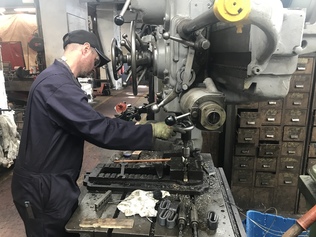
Paul did this job on the Bridgeport milling machine. At last, we are allowed back in the workshops at Boston Lodge and can use all the machine tools.
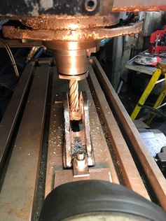
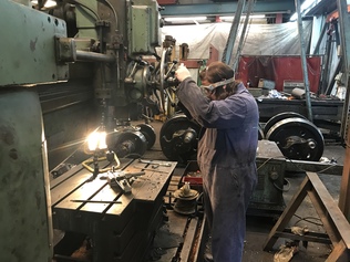
The ratchet drill set up to ream the mounting holes for the steam brake cylinder.
Dave 2 reams the brake cylinder holes.
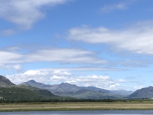
A beautiful June day in Wales, the view of Snowdon from the Cob. In the middle of the photo, an Osprey circles over the River Glaslyn looking for its lunch. We are so lucky to have a railway workshop that looks out over this panorama! (The Osprey, one of the UK's largest and rarest birds of prey, did catch a big fish for lunch too)
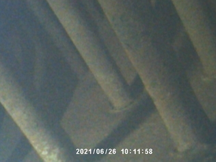
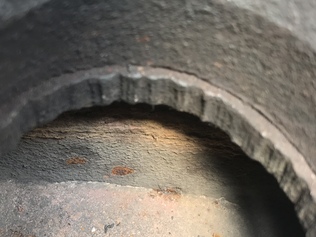
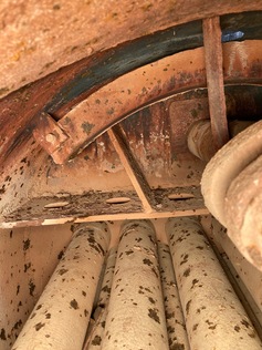
Endosope view of the flexible stays passing through the outer firebox wrapper, from the inside.
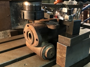
The turbogenerator steam regulator housing, set up on the milling machine to drill out a seized grub screw that located the valve sleeve.
Andrew completed manufacture of the boiler diaphragm plate bracket and is seen here putting a coat of primer on it. Soon this will be welded to the main frames.
Chris explores the inside of the firebox with an endoscope.
View down into the top feed, showing the distribution tray for the feedwater.
Andrew drills holes for split pins in the new brake pins.
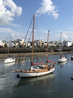
As a change from the usual view of Snowdon, here are some yachts in Porthmadog harbour at the weekend. Many of the group are social members of the Madoc Yacht Club and their harbourside beer garden was a great place for an after-work drink in the sun with friends.
Helen drills holes in the heads of the long pins used to retain the brake block carrier pins.
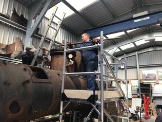
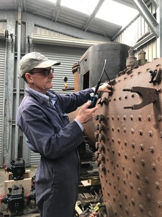
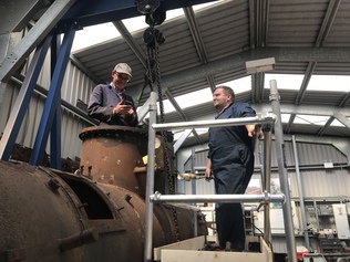
Byron unbolts the lid of the dome, with Chris monitoring progress.
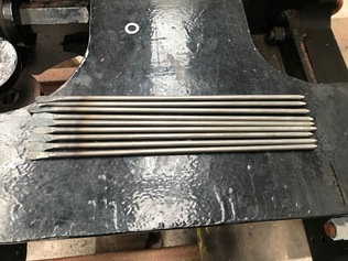
Brake pins cut to length and drilled.
Andrew machines up a simple jig for making the brake pins to the correct length.
Chris stands inside the dome, checking some photos he had just taken with his phone, while Byron looks on.
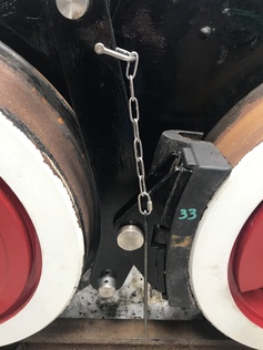
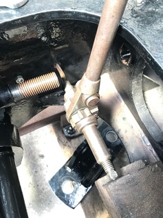
Brake block carrier pin retaining assembly. The long thin pin drops through a hole in the back of the horizontal pin to stop it working loose.
On all the other pins this role is filled by a split pin, but behind the brake gear and the motion it would be inaccessible.
On Sunday, the Lyd disgraced itself by failing in section with a passenger train. With so many volunteers at Boston Lodge, we had no trouble crewing the Vale of Ffestiniog to rescue the train and complete its journey, while Upnor Castle went to retrieve the errant kettle.
Looking through a mudhole door in the outer firebox, showing flexible stays entering the top of the inner firebox. Also, in the dentist's mirror, a view of the other end of one of the stays where it passes into a cup set into the outer wrapper.
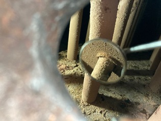
Looking forward from the dome inside the top of the boiler. The crescent-shaped top feed water distribution tray is visible over the main steam pipe. Behind that is the front tubeplate stiffener, and at the bottom of the photo the superheater flues are visible.
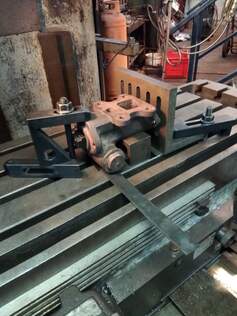
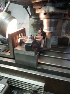
A complex clamping arrangement for skimming the main mounting face.
Cleaning up the threads in the filter housing.
Milling the joint face for the adjuster cap.
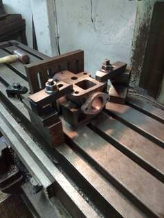
The turbogenerator regulator body is now fully stripped down and cleaned up.
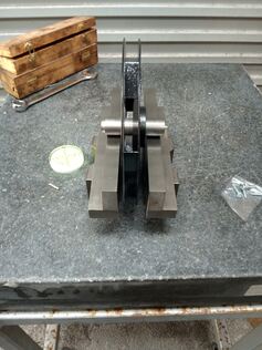
The Turbine cooling fan was checked for static balancing using a leveled surface plate. Small magnetic weights were applied and the fan allowed to rotate. Eventually found that no weights were needed. The fan has now been fitted to the Generator.
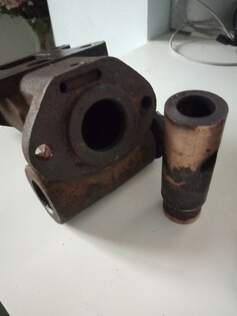
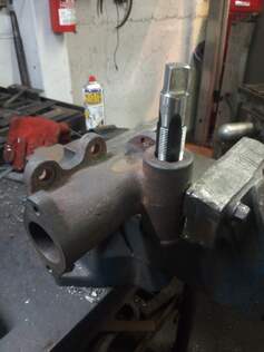
The piston sleeve finally removed from the housing.
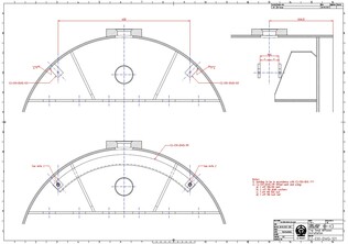
From the photos and measurements taken by Chris and Byron, Dave prepared a draft drawing of the top feed arrangement inside the boiler.
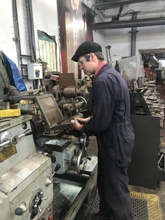
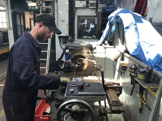
Ed uses a lathe to face off lengths of stainless steel bar for brake gear pins.